Multifan Wiring Diagram

Free Shipping For Ebm Papst Multifan 4412m Dc 12v 2 7w 2 Wire 2
Multifan 4e50 20 Panel Fan

Ad Ebay Multifan Standard Performance Panel Fan 16in Dia
Multifan 8d92 36 Three Phase Panel Fan
Multifan 4d152 50 Three Phase Box Fan With Casing And Shutter

Multifan 130 Vostermans Ventilation Pdf Catalogs Technical
The multifan varifan electric automatic speed control is a variable speed control with manual adjustment of fan speed and temperature selection.
Multifan wiring diagram. The wire colors in a basic fan light kit are typically black blue white and green. Technische gegevens 1 5 hp modellen multifan 130 with 3 blades multifan 130 with 5 blades i multifan 130 with cone 3 blades i multifan 130 with cone 5 blades ultifan 130 with 3 blades multifan 130 with 5 blades multifan 130 with cone 3 blades multifan 130 with cone 5 blades n sound pressure level measured at 7 m. Section a ecs 5c multifan. Switched lines and neutral connect to a 3 wire cable that travels to the light fan outlet box in the ceiling the fan control switch usually connects to the black wire and the light kit switch to the red wire of the 3 way cable in this diagram the black wire of the ceiling fan is for the fan and the blue wire.
Ceiling fans and light kits dimmer switches fan speed controllers 3 way fan switches and bathroom exhaust fan circuits. Electrical question from mike about multi speed fan wiring background. It has 5 wires coming from the motor 1 black 2 white 1 red 1 green. Line voltage enters the switch outlet box and the line wire connects to each switch.
View and download multifan t15 wd instruction manual online. Installing a ceiling fan. Start your wiring project by taking both of the positive wires from the fans and run them to the yellow wires on each relay tab 87. Wiring diagram 1 power enters at the wall switch box power starting at the switch box this wiring diagram shows the power starting at the switch box where a splice is made with the hot line which passes the power to both switches and up to the ceiling fan and light.
T15 wd thermostat pdf manual download. This page contains wiring diagrams for household fans including. I have a old 4 bladed steel fan. It shows the components of the circuit as simplified forms and also the power and also signal links between the gadgets.
3ø wiring diagrams 1ø wiring diagrams diagram er9 m 3 1 5 9 3 7 11 low speed high speed u1 v1 w1 w2 u2 v2 tk tk thermal overloads two speed star delta motor switch m 3 0 10v 20v 415v ac 4 20ma outp uts diagram ic2 m 1 240v ac 0 10v outp ut diagram ic3 m 1 0 10v 4 20ma 240v ac outp uts these diagrams are current at the time of publication. Assortment of ebm papst motor wiring diagram. It uses a 40 amp electric relay and electric fan sensor.
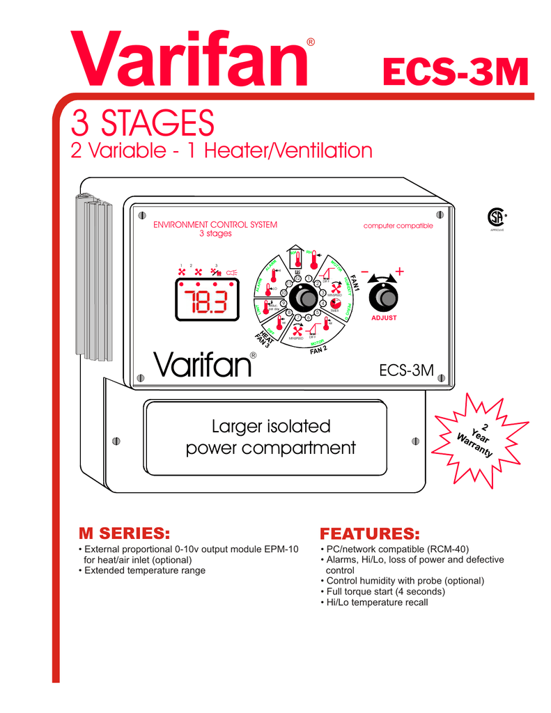
Multifan Varifan Ecs 3m Information Sheet Manualzz
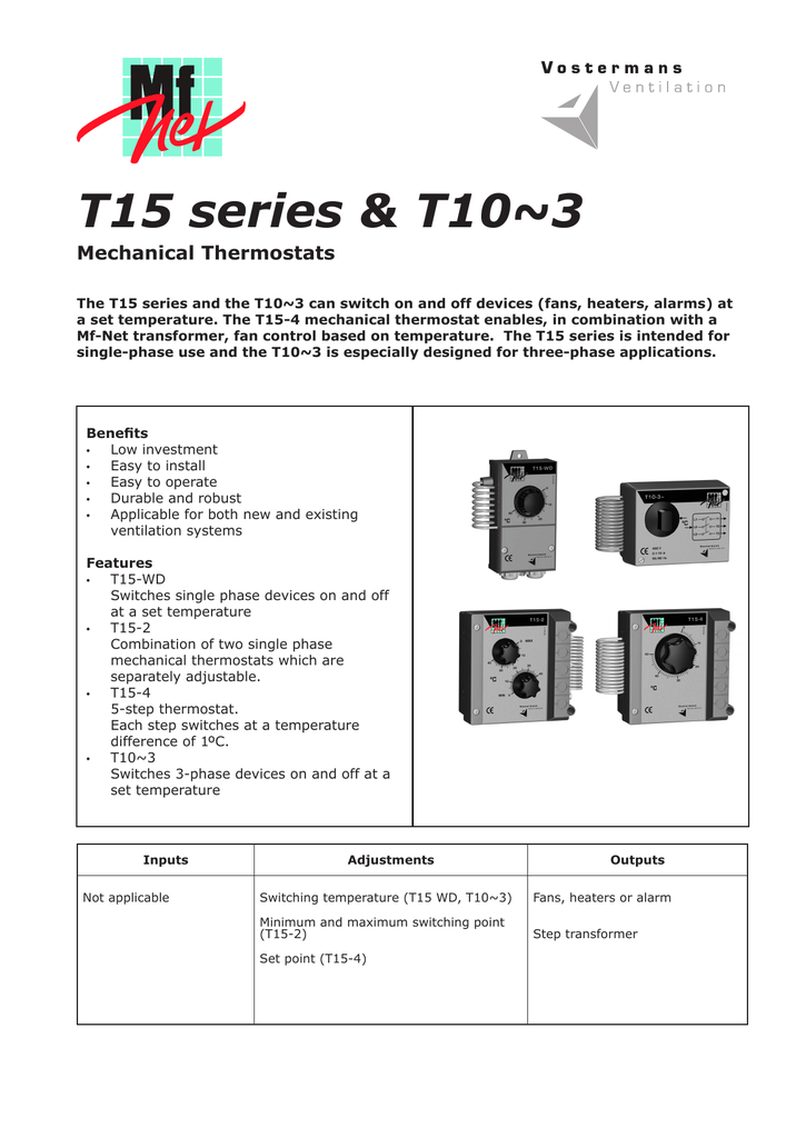
Multifan T15 2 Two Stage Thermostat Information Sheet Manualzz

Multifan T15 Wd Thermostat Tt15wdcam1a By Multifan 31 25

Ventilation Back To Website Fan Selector Article Selector My

Multifan System Emc Motors

Multifan Brochure Vostermans Ventilation Pdf Catalogs

Newest Rgb Chassis Fan Control Card Hub Rgb Fan Adapter Multi Fan

Multifan V Flofan For Medical Cannabis Youtube

Carrier 42 Cet Fcu Mechanical Fan Duct Flow
Https Urban Gro Com Wp Content Uploads 2019 07 Multifan Panel Fan 120v V Dec 2018 Pdf
Https Www Northerntool Com Images Downloads Manuals 43897 Pdf
Http Www Farmtek Com Wcsstore Engineeringservices Allbizunits Techdocs 116423 24 Pdf
