Muncie Pto Pressure Switch Wiring Diagram
Best Practices For Wiring A Pto Trailer Body Builders
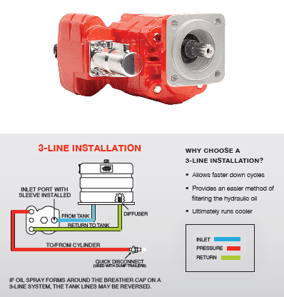
Types Of Hydraulic Pumps
Https Www Munciepower Com Cms Files Products Literature Documents Service Parts Sp97 01 Pdf

Pto Installation And Owner S Manual Muncie Power

Pin On Hydraulic Parts

Safeway Hydraulic Winged Coupler Safeway S S51 Series Is A Minimum

Remove the installation kit 43tk5282 components from the fa6b pto carton.
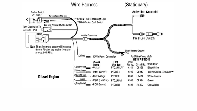
Muncie pto pressure switch wiring diagram. Check for gaps between the pto and. It shows the components of the circuit as streamlined shapes and also the power as well as signal connections between the tools. 5 green light should activate. Locate the straight fitting 43t36431 and the elbow fitting.
Plug in the molded connector to the back of switch per the 48tk3981 wiring diagram. Section 2 wiring diagrams and auxiliary wiring instructions. The green wire in back of connector is up. Also check the fa6b pto driver gear for condition.
It shall be the responsibility of the installer of a muncie power take off to. Never get under this truck if the engine is running. Variety of pto switch wiring diagram. Standard h shift option model years standard muncie power products is a leading manufacturer of power take offs pto hydraulic components such as pumps motors cylinders valves and reservoirs and snow ice removal products.
A nick or blemish may cause excessive noise when the fa6b pto is mounted. A wiring diagram is a simplified conventional pictorial representation of an electrical circuit. It shall be the responsibility of the installer of a muncie power take off. Muncie pto pressure switch wiring diagram release pto switch.
Engage pto with switch. Pto installation and operator s manual keep in vehicle. For the cs series install the pressure switch before mounting the pto. Pto installation owner s manual for muncie fa series pto used on the ford 4r100 automatic transmission.
The muncie power take off is warranted to be free of defects in. The cs20 cs22 cs24 cs26 pressure switch may need to be mounted with fitting and elbow to clear the transmission case.
Https Www Munciepower Com Cms Files Products Literature Documents Service Parts Sp18 02 Ssh Ssv Split Shaft Pto Service Pdf

Pressure Compensated Pump Adjustments Part 1 Youtube

How To Repair A Pto Solenoid Coil That Got Hot Youtube
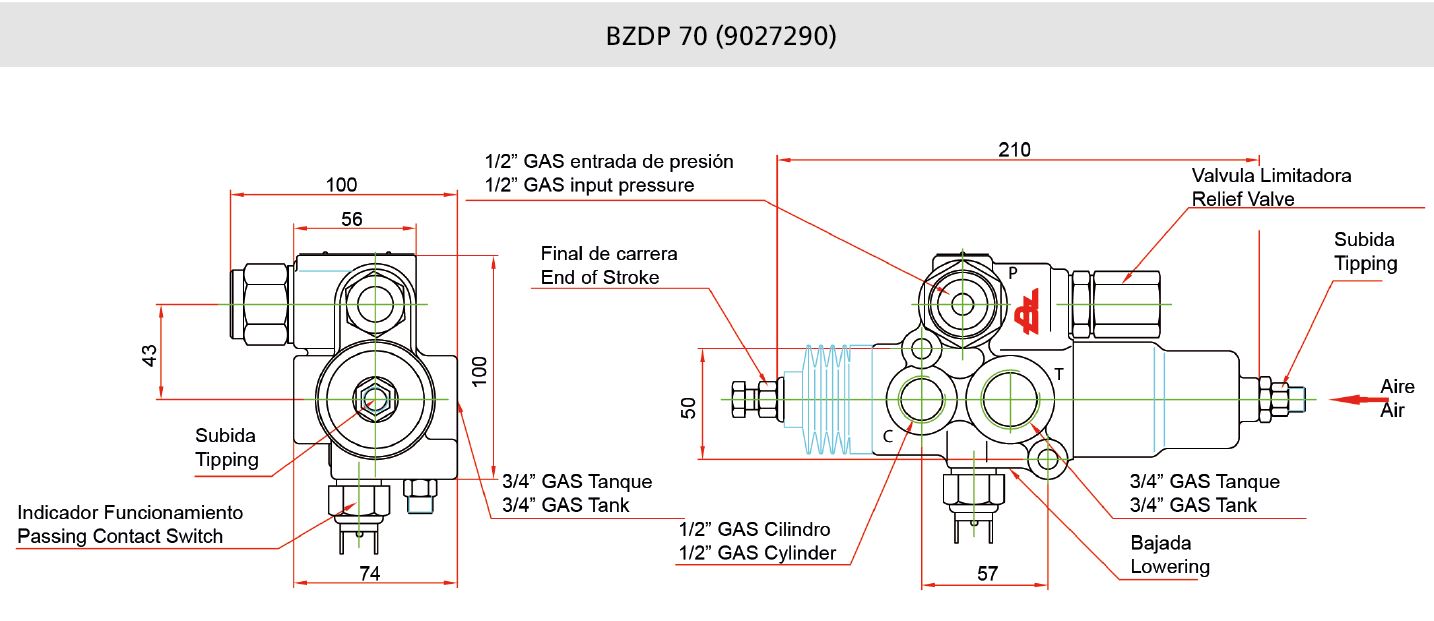
9027290 Bzdp Bzv 70 Tipping Valve Bezares Sa

Troubleshooting A Water Pressure Bladder Tank Pressure Tanks

Adjusting Pressure Relief Valve Pressure Youtube

Electric Clutch Installation For Small Hydraulic Pumps Youtube
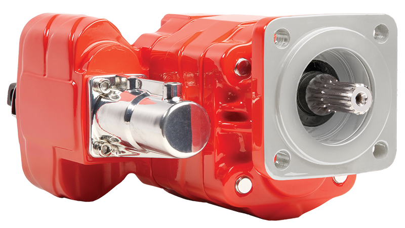
E Series Dump Pump

Diagnosing Low Pressure In A Hydraulic System Youtube

Hydraulic Gear Pumps Explained Youtube
Problematic Pto Remove Teardown Repair Youtube

3 To 5 Ton Drive Products
